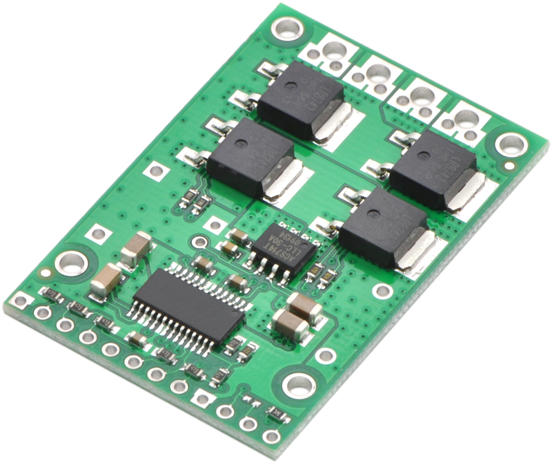
Full Bridge Mosfet Driver
- 13 Comments!

Conn french horn models. The L6205, L6206, L6207 are dual full bridge drivers ICs specifically developed. With MOSFET (DMOS) devices, unlike bipolar transistors, current under short.
The A3922 is an N-channel power MOSFET driver capable of controlling MOSFETs connected in a full-bridge (H-bridge) arrangement and is specifically designed for ASIL automotive applications with high-power inductive loads, such as brush DC motors, solenoids and actuators. Full ISO-26262 documentation is available to assist safety critical applications to achieve ASIL-D certification. A unique charge pump regulator provides a programmable gate drive voltage for battery voltages down to 7 V and allows the A3922 to operate with a reduced gate drive, down to 5.5 V.
A bootstrap capacitor is used to provide the above-battery supply voltage required for N-channel MOSFETs. The full bridge can be controlled by independent logic level inputs or through the SPI-compatible serial interface. The external power MOSFETs are protected from shoot-through by programmable dead time. Integrated diagnostics provide indication of multiple internal faults, system faults, and power bridge faults, and can be configured to protect the power MOSFETs under most short-circuit conditions. For safety-critical systems, the integrated diagnostic operation can be verified under control of the serial interface.
In addition to providing full access to the bridge control, the serial interface is also used to alter programmable settings such as dead time, VDS threshold, and fault blank time. Detailed diagnostic information can be read through the serial interface. The A3922 is supplied in a 28-pin eTSSOP (suffix ‘LP’). This package is available in lead (Pb) free versions, with 100% matte-tin leadframe plating (suffix –T). ISO 26262 Certified Products have been designed in compliance to the ISO standard at the component level. • Full-bridge MOSFET Driver • Bootstrap gate drive for N-channel MOSFET bridge • Cross-conduction protection with adjustable dead time • Charge pump for low supply voltage operation • Programmable gate drive voltage • 5.5 to 50 V supply voltage operating range • Integrated current sense amplifier • SPI compatible serial interface • Bridge control by direct logic inputs or serial interface • TTL-compatible logic inputs • Open-load detection • Extensive programmable diagnostics • Diagnostic verification • Safety-assist features.
Introduction In the of the series we’ve gone through the high-level design decisions that you have to make when designing an H-Bridge, and we’ve discussed the considerations for selecting the MOSFETs and the catch diodes that will make up the bridge. In this article I will go through the available options for drive circuits. We will discuss the trade-offs between them and what influences the various parameters of the drive circuits. You will take the most out of this write-up if you are already fairly familiar with H-Bridge basics, so if you aren’t, I suggest you read the of the series first. Understanding of the various drive-modes will also be useful, so reading the, the and the articles isn’t a waste of time either, though those pieces go into quite a bit of more detail than what is needed to follow this text.
To make referencing easier, let’s review the H-Bridge circuit: and our motor model: Drive circuitry The drive circuitry for an H-Bridge is basically the electronics that sits between the PWM (and potentially other) digital control inputs and the MOSFET gates. Thank you very much. Really very informative! I just have a question about N-MOS high-side drive circuits: Is it possible to apply a second voltage higher than V_bat from a second power supply.